19 KiB
Addressable RGB LEDs
HomeSpan includes two dedicated classes that provide for easy control of "addressable" RGB LEDs. The Pixel() class is used for RGB and RGBW LEDs that require only a single "data" control wire, such as this 8-pixel NeoPixel RGB Stick or this single-pixel NeoPixel RGBW LED. The Dot() class is used for RGB LEDs that require two control wires ("data" and "clock"), such as this 144-pixel DotStar RGB Strip or this 60-pixel RGB LED Strip.
Both classes allow you to individually set each of the "pixels" in a multi-pixel LED strip to a different 24-bit RGB color (or 32-bit color, if using RGBW LEDs). Alternatively, the classes allow you to simply specify a single 24-bit (or 32-bit) color to duplicate across all pixels.
The methods for both classes are nearly identical, which allows you to readily interchange code written for single-wire devices to use with two-wire devices (and vice-versa) with only minor modifications.
Both classes are provided in a standalone header file that is accessed by placing the following near the top of your sketch:
#include "extras/Pixel.h"
Pixel(uint8_t pin, [boolean isRGBW])
Creating an instance of this class configures the specified pin to output a waveform signal suitable for a controlling single-wire, addressable RGB or RGBW LEDs. Arguments, along with their defaults if left unspecified, are as follows:
- pin - the pin on which the RGB control signal will be output; normally connected to the "data" input of the addressable LED device
- isRGBW - set to true for RGBW devices that contain 4-color (red/green/blue/white) LEDs; set to false for the more typical 3-color RGB devices. Defaults to false if unspecified. Note you must set the isRGBW flag to true if you are using an RGBW device, even if you do not intend on utilizing the white LED
The following methods are supported:
-
void set(Color color, int nPixels=1)- sets the color of a pixel in a single-pixel device, or equivalently, the color of the first nPixels in a multi-pixel device, to color, where color is a structure of type Color defined below. If unspecified, nPixels defaults to 1 (i.e. a single pixel). It is not a problem if the value specified for nPixels does not match the total number of actual RGB (or RGBW) pixels in your device; if nPixels is less than the total number of device pixels, only the first nPixels will be set to color; if nPixels is greater than the total number of device pixels, the device will simply ignore the additional input
-
void set(Color *color, int nPixels)- individually sets the color of each pixel in a multi-pixel device to the color values specified in the Color array *color, of nPixels size, where the first pixel of the device is set to the value in color[0], the second pixel is set to the value in color[1] ... and the last pixel is set to the value in color[nPixels-1]. The number of pixels in *color array, nPixels, must be specified. Similar to above, it is not a problem if the value specified for nPixels does not match the total number of actual RGB (or RGBW) pixels in your device; if nPixels is less than the total number of device pixels, only the first nPixels will be set to the values in the *color array; if nPixels is greater than the total number of device pixels, the device will simply ignore the additional input
-
static Color RGB(uint8_t r, uint8_t g, uint8_t b, uint8_t w=0) -
returns a Color object, where r, g, and b, represent 8-bit red, green, and blue values over the range 0-255, and w represents an 8-bit value [0-255] for the white LED. The white value may be left unspecified, in which case it defaults to 0. Also, the white value will be ignored by set() unless the isRGBW flag was specified as true in the constructor
-
static Color HSV(float h, float s, float v, double w=0) -
returns a Color object after converting the values of h (a Hue from 0-360), s (a Saturation percentage from 0-100), and v (a Brightness percentage from 0-100) to equivalent 8-bit RGB values, each from 0-255. The w value is treated separately and represents a percentage of brightness for the white LED (from 0-100) that is subsequently converted into an 8-bit value from 0-255. The white value may be left unspecified, in which case it defaults to 0. Also, the white value will be ignored by set() unless the isRGBW flag was specified as true in the constructor
-
int getPin()- returns the pin number (or -1 if the instantiation failed due to lack of resources - see below)
-
void setTiming(float high0, float low0, float high1, float low1, uint32_t lowReset)- the waveform that the set() methods generate to set the color(s) of an RGB or RGBW device are calibrated to work with most commercial devices. However, if you have a device that utilizes non-standard pulses, you may use setTiming() to specify a custom pulse width, where
LedPin also includes a static class function that converts Hue/Saturation/Brightness values (typically used by HomeKit) to Red/Green/Blue values (typically used to control multi-color LEDS).
-
static void HSVtoRGB(float h, float s, float v, float *r, float *g, float *b)- h - input Hue value, range 0-360
- s - input Saturation value, range 0-1
- v - input Brightness value, range 0-1
- r - output Red value, range 0-1
- g - output Green value, range 0-1
- b - output Blue value, range 0-1
See tutorial sketch #10 (RGB_LED) for an example of using LedPin to control an RGB LED.
ServoPin(uint8_t pin [,double initDegrees [,uint16_t minMicros, uint16_t maxMicros, double minDegrees, double maxDegrees]])
Creating an instance of this class configures the specified pin to output a 50 Hz PWM signal, which is suitable for controlling most Servo Motors. There are three forms of the constructor: one with just a single argument; one with two arguments; and one with all six arguments. Arguments, along with their defaults if left unspecified, are as follows:
- pin - the pin on which the PWM control signal will be output. The control wire of a Servo Motor should be connected this pin
- initDegrees - the initial position (in degrees) to which the Servo Motor should be set (default=0°)
- minMicros - the pulse width (in microseconds) that moves the Servo Motor to its "minimium" position of minDegrees (default=1000𝛍s)
- maxMicros - the pulse width (in microseconds) that moves the Servo Motor to its "maximum" position of maxDegrees (default=2000𝛍s)
- minDegrees - the position (in degrees) to which the Servo Motor moves when receiving a pulse width of minMicros (default=-90°)
- maxDegrees - the position (in degrees) to which the Servo Motor moves when receiving a pulse width of maxMicros (default=90°)
The minMicros parameter must be less than the maxMicros parameter, but setting minDegrees to a value greater than maxDegrees is allowed and can be used to reverse the minimum and maximum positions of the Servo Motor. The following methods are supported:
-
void set(double position)- sets the position of the Servo Motor to position (in degrees). In order to protect the Servo Motor, values of position less than minDegrees are automatically reset to minDegrees, and values greater than maxDegrees are automatically reset to maxDegrees.
-
int getPin()- returns the pin number (or -1 if ServoPin was not successfully initialized)
A worked example showing how ServoPin can be used to control the Horizontal Tilt of a motorized Window Shade can be found in the Arduino IDE under File → Examples → HomeSpan → Other Examples → ServoControl.
PWM Resource Allocation and Limitations
The following PWM resources are available:
- ESP32: 16 Channels / 8 Timers (arranged in two distinct sets of 8 Channels and 4 Timers)
- ESP32-S2: 8 Channels / 4 Timers
- ESP32-C3: 6 Channels / 4 Timers
HomeSpan automatically allocates Channels and Timers to LedPin and ServoPin objects as they are instantiated. Every pin assigned consumes a single Channel; every unique frequency specified among all channels (within the same set, for the ESP32) consumes a single Timer. HomeSpan will conserve resources by re-using the same Timer for all Channels operating at the same frequency. HomeSpan also automatically configures each Timer to support the maximum duty-resolution possible for the frequency specified.
HomeSpan will report a non-fatal error message to the Arduino Serial Monitor when insufficient Channel or Timer resources prevent the creation of a new LedPin or ServoPin object. Calls to the set() method for objects that failed to be properly created are silently ignored.
Remote Control Radio Frequency / Infrared Signal Generation
The ESP32 has an on-chip signal-generator peripheral designed to drive an RF or IR transmitter. HomeSpan includes an easy-to-use library that interfaces with this peripheral so that with a few additional electronic components you can create a HomeSpan device that controls an RF or IR appliance directly from the Home App on your iPhone, or via Siri. The library is accessed the following near the top of your sketch:
#include "extras/RFControl.h"
RFControl(int pin, boolean refClock=true)
Creating an instance of this class initializes the RF/IR signal generator and specifies the ESP32 pin to output the signal. You may create more than one instance of this class if driving more than one RF/IR transmitter (each connected to different pin), subject to the following limitations: ESP32 - 8 instances; ESP32-S2 - 4 instances; ESP32-C3 - 2 instances. The optional parameter refClock is more fully described further below under the start() method.
Signals are defined as a sequence of HIGH and LOW phases that together form a pulse train where you specify the duration, in ticks, of each HIGH and LOW phase, shown respectively as H1-H4 and L1-L4 in the following diagram:
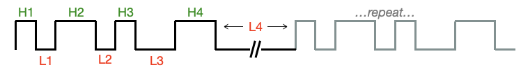
Since most RF/IR signals repeat the same train of pulses more than once, the duration of the last LOW phase should be extended to account for the delay between repeats of the pulse train. Pulse trains are encoded as sequential arrays of 32-bit words, where each 32-bit word represents an individual pulse using the following protocol:
- bits 0-14: the duration, in ticks from 0-32767, of the first part of the pulse to be transmitted
- bit 15: indicates whether the first part of the pulse to be trasnmitted is HIGH (1) or LOW (0)
- bits 16-30: the duration, in ticks from 0-32767, of the second part of the pulse to be transmitted
- bit 31: indicates whether the second part of the pulse to be trasnmitted is HIGH (1) or LOW (0)
HomeSpan provides two easy methods to create, store, and transmit a pulse train. The first method relies on the fact that each instance of RFControl maintains its own internal memory structure to store a pulse train of arbitrary length. The functions clear(), add(), and pulse(), described below, allow you to create a pulse train using this internal memory structure. The start() function is then used to begin transmission of the full pulse train. This method is generally used when pulse trains are to be created on-the-fly as needed, since each RFControl instance can only store a single pulse train at one time.
In the second method, you create one or more pulse trains in external arrays of 32-bit words using the protocol above. To begin transmission of a specific pulse train, call the start() function with a pointer reference to the external array containing that pulse train. This method is generally used when you want to pre-compute many different pulse trains and have them ready-to-transmit as needed. Note that this method requires the array to be stored in RAM, not PSRAM.
Details of each function are as follows:
-
void clear()- clears the pulse train memory structure of a specific instance of RFControl
-
void phase(uint32_t numTicks, uint8_t phase)-
appends either a HIGH or LOW phase to the pulse train memory buffer for a specific instance of RFControl
-
numTicks - the duration, in ticks of the pulse phase. Durations of greater than 32767 ticks allowed (the system automatically creates repeated pulses of a maximum of 32767 ticks each until the specified duration of numTicks is reached)
-
phase - set to 0 to create a LOW phase; set to 1 (or any non-zero number) to create a HIGH phase
-
-
repeated phases of the same type (e.g. HIGH followed by another HIGH) are permitted and result in a single HIGH or LOW phase with a duration equal to the sum of the numTicks specified for each repeated phase (this is helpful when generating Manchester-encoded signals)
-
-
void add(uint32_t onTime, uint32_t offTime)- appends a single HIGH/LOW pulse with duration onTime followed by offTime to the pulse train of a specific instance of RFControl. This is functionally equivalent to calling
phase(onTime,HIGH);followed byphase(offTime,LOW);as defined above
- appends a single HIGH/LOW pulse with duration onTime followed by offTime to the pulse train of a specific instance of RFControl. This is functionally equivalent to calling
-
void enableCarrier(uint32_t freq, float duty=0.5)-
enables modulation of the pulse train with a "square" carrier wave. In practice this is only used for IR signals (not RF)
-
freq - the frequency, in Hz, of the carrier wave. If freq=0, carrier wave is disabled
-
duty - the duty cycle of the carrier wave, from 0-1. Default is 0.5 if not specified
-
-
RFControl will report an error if the combination of the specified frequency and duty cycle is outside the range of supported configurations
-
-
void disableCarrier()- disables the carrier wave. Equivalent to
enableCarrier(0);
- disables the carrier wave. Equivalent to
-
void start(uint8_t _numCycles, uint8_t tickTime) -
void start(uint32_t *data, int nData, uint8_t nCycles, uint8_t tickTime) -
in the first variation, this starts the transmission of the pulse train stored in the internal memory structure of a given instance of RFControl that was created using the
clear(),add(), andphase()functions above. In the second variation, this starts the transmission of the pulse train stored in an external array data containing nData 32-bit words. The signal will be output on the pin specified when RFControl was instantiated. Note this is a blocking call—the method waits until transmission is completed before returning. This should not produce a noticeable delay in program operations since most RF/IR pulse trains are only a few tens-of-milliseconds long-
numCycles - the total number of times to transmit the pulse train (i.e. a value of 3 means the pulse train will be transmitted once, followed by 2 additional re-transmissions). This is an optional argument with a default of 1 if not specified.
-
tickTime - the duration, in clock units, of a tick. This is an optional argument with a default of 1 clock unit if not specified. Valid range is 1-255 clock units, or set to 0 for 256 clock units. The duration of a clock unit is determined by the refClock parameter (the second, optional argument, in the RFControl constructor described above). If refClock is set to true (the default), RFControl uses the ESP32's 1 MHz Reference Clock for timing so that each clock unit equals 1𝛍s. If refClock is set to false, RFControl uses the ESP32's faster 80 MHz APB Clock so that each clock unit equals 0.0125𝛍s (1/80 of microsecond)
-
-
To aid in the creation of a pulse train stored in an external array of 32-bit words, RFControl includes the macro RF_PULSE(highTicks,lowTicks) that returns a properly-formatted 32-bit value representing a single HIGH/LOW pulse of duration highTicks followed by lowTicks. This is basically an analog to the
add()function. For example, the following code snippet shows two ways of creating and transmitting the same 3-pulse pulse-train --- the only difference being that one uses the internal memory structure of RFControl, and the second uses an external array:
RFControl rf(11);  // create an instance of RFControl

rf.clear();        // clear the internal memory structure
rf.add(100,50);    // create pulse of 100 ticks HIGH followed by 50 ticks LOW
rf.add(100,50);    // create a second pulse of 100 ticks HIGH followed by 50 ticks LOW
rf.add(25,500);    // create a third pulse of 25 ticks HIGH followed by 500 ticks LOW
rf.start(4,1000);  // start transmission of the pulse train; repeat for 4 cycles; one tick = 1000𝛍s

uint32_t pulseTrain[] = {RF_PULSE(100,50), RF_PULSE(100,50), RF_PULSE(25,500)};    // create the same pulse train in an external array
rf.start(pulseTrain,3,4,1000);  // start transmission using the same parameters
Example RFControl Sketch
Below is a complete sketch that produces two different pulse trains with the signal output linked to the ESP32 device's built-in LED (rather than an RF or IR transmitter). For illustrative purposes the tick duration has been set to a very long 100𝛍s, and pulse times range from of 1000-10,000 ticks, so that the individual pulses are easily discernable on the LED. Note this example sketch is also available in the Arduino IDE under File → Examples → HomeSpan → Other Examples → RemoteControl.
/* HomeSpan Remote Control Example */

#include "HomeSpan.h"             // include the HomeSpan library
#include "extras/RFControl.h"     // include RF Control Library

void setup() {

  Serial.begin(115200);           // start the Serial interface
  Serial.flush();
  delay(1000);                    // wait for interface to flush

  Serial.print("\n\nHomeSpan RF Transmitter Example\n\n");

  RFControl rf(13);               // create an instance of RFControl with signal output to pin 13 on the ESP32

  rf.clear();                     // clear the pulse train memory buffer

  rf.add(5000,5000);              // create a pulse train with three 5000-tick high/low pulses
  rf.add(5000,5000);
  rf.add(5000,10000);             // double duration of final low period

  Serial.print("Starting 4 cycles of three 500 ms on pulses...");

  rf.start(4,100);                // start transmission of 4 cycles of the pulse train with 1 tick=100 microseconds

  Serial.print("Done!\n");

  delay(2000);

  rf.clear();

  for(int i=1000;i<10000;i+=1000)
    rf.add(i,10000-i);
  rf.add(10000,10000);

  Serial.print("Starting 3 cycles of 100-1000 ms pulses...");

  rf.start(3,100);                // start transmission of 3 cycles of the pulse train with 1 tick=100 microseconds

  Serial.print("Done!\n");

  Serial.print("\nEnd Example");

} // end of setup()

void loop(){

} // end of loop()
↩️ Back to the Welcome page