3.1 KiB
HomeSpan Extras
HomeSpan includes integrated access to a number of ESP32 features you'll likely find particularly useful when constructing your HomeSpan devices.
Pulse Width Modulation (PWM)
PWM on the ESP32 is more flexible, but slighly more complicated, than PWM on most Arduino devices (like the Uno or Mega). On the ESP32, you use one of 16 built-in timer-channels to create a PWM signal, and then link that channel to any ESP32 pin. HomeSpan includes a library that makes this very easy, and is accessed as by placing the following near the top of your sketch:
#include "extras/PwmPin.h"
PwmPin(uint8_t channel, uint8_t pin)
Creating an instance of this class links one of 16 timer-channels to an ESP32 pin.
- channel - the ESP32 timer-channel number (0-15) to generate the PWM signal
- pin - the ESP32 pin that will output the PWM signal produced by the channel
The following methods are supported:
-
void set(uint8_t channel, uint8_t level)- sets the PWM %duty-cycle of timer-channel channel (0-15) to level, where level ranges from 0 (off) to 100 (steady on)
-
int getPin()- returns the pin number
PwmPin also includes a static class function that converts Hue/Saturation/Brightness values (typically used by HomeKit) to Red/Green/Blue values (typically used to control multi-color LEDS).
-
static void HSVtoRGB(float h, float s, float v, float *r, float *g, float *b)- h - input Hue value, range 0-360
- s - input Saturation value, range 0-1
- v - input Brightness value, range 0-1
- r - output Red value, range 0-1
- g - output Green value, range 0-1
- b - output Blue value, range 0-1
See tutorial sketch #10 (RGB_LED) for an example of using PwmPin to control an RGB LED.
Radio Frequency / Infrared Signal Generation
The ESP32 has an on-chip signal-generator peripheral designed to drive an RF or IR transmitter. HomeSpan includes an easy-to-use library that interfaces with this peripheral so that with a few additional electronic components you can create a HomeSpan device that controls an RF or IR appliance directly from the Home App on your iPhone, or via Siri. The library is accessed the following near the top of your sketch:
#include "extras/RFControl.h"
RFControl(int pin)
Creating an instance of this class initializes the RF/IR signal generator and specifies the ESP32 pin to output the signal. You may create more than one instance of this class if driving more than one RF/IR transmitter (each connected to different pin).
Signals are defined as a sequence of pulses, where you specify the duration, in ticks, of each individual HIGH and LOW period, shown respectively as H1-H4, and L1-L4, in the diagram below.
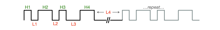
Since most RF/IR signals repeat the same train of pulses more than once, the duration of the last LOW period should be extended to account for the delay between repeats of the pulse train. The following methods are used to define the pulse train, set the number of repeats, set the duration of a tick, and start the transmission:
↩️ Back to the Welcome page