9.7 KiB
HomeSpan Extras
HomeSpan includes integrated access to a number of ESP32 features you'll likely find particularly useful when constructing your HomeSpan devices.
Pulse Width Modulation (PWM)
The ESP32 has 16 PWM channels that can be used to drive a variety of devices. HomeSpan includes an integrated PWM library with dedicated classes designed for controlling Dimmable LEDs as well as Servo Motors. Both classes are provided in a standalone header file that is accessd by placing the following near the top of your sketch:
#include "extras/PwmPin.h"
LedPin(uint8_t pin)
Creating an instance of this class configures the specified pin to output a 5000 Hz PWM signal, which is suitable for dimming LEDs. The following methods are supported:
-
void set(uint8_t level)- sets the PWM %duty-cycle to level, where level ranges from 0 (LED completely off) to 100 (LED fully on)
-
int getPin()- returns the pin number
LedPin also includes a static class function that converts Hue/Saturation/Brightness values (typically used by HomeKit) to Red/Green/Blue values (typically used to control multi-color LEDS).
-
static void HSVtoRGB(float h, float s, float v, float *r, float *g, float *b)- h - input Hue value, range 0-360
- s - input Saturation value, range 0-1
- v - input Brightness value, range 0-1
- r - output Red value, range 0-1
- g - output Green value, range 0-1
- b - output Blue value, range 0-1
See tutorial sketch #10 (RGB_LED) for an example of using LedPin to control an RGB LED.
ServoPin(uint8_t pin [,double initDegrees [,uint16_t minMicros, uint16_t maxMicros, double minDegrees, double maxDegrees]])
Creating an instance of this class configures the specified pin to output a 50 Hz PWM signal, which is suitable for controlling most Servo Motors. There are three forms of the constructor: one with just a single argument; one with two arguments; and one with all six arguments. Arguments, along with their defaults if left unspecified, are as follows:
- pin - the pin on which the PWM control signal will be output. The control wire of a Servo Motor should be connected this pin
- initDegrees - the initial position (in degrees) to which the Servo Motor should be set (default=0°)
- minMicros - the pulse width (in microseconds) that moves the Servo Motor to its "minimium" position of minDegrees (default=1000𝛍s)
- maxMicros - the pulse width (in microseconds) that moves the Servo Motor to its "maximum" position of maxDegrees (default=2000𝛍s)
- minDegrees - the position (in degrees) to which the Servo Motor moves when receiving a pulse width of minMicros (default=—90°)
- maxDegrees - the position (in degrees) to which the Servo Motor moves when receiving a pulse width of maxMicros (default=90°)
The minMicros parameter must be less than the maxMicros parameter, but setting minDegrees to a value greater than maxDegrees is allowed and can be used to reverse the minimum and maximum positions of the Servo Motor. The following methods are supported:
-
void set(uint8_t position)- sets the position of the Servo Motor to position (in degrees). In order to protect the Servo Motor, values of position less than minDegrees are automatically reset to minDegrees and value greater than maxDegrees are automatically reset to maxDegrees.
-
int getPin()- returns the pin number
A worked example showing how ServoPin can be used to control the Horizontal Tilt of a motorized Window Shade can be found in the Arduino IDE under File → Examples → HomeSpan → Other Examples → ServoControl.
Resource limitations:
- A maximum of 16 LedPin objects can be instantiated
- A maximum of 8 ServoPin objects can be instantiated
- A maximum combined total of 16 LedPin and ServoPin objects can be instantiated (for example 10 LedPin and 6 ServoPin objects)
HomeSpan will report a non-fatal error message to the Arduino Serial Monitor for each LedPin or ServoPin that instantiated beyond these limits. Calls to the set() method for objects that exceed these limits are ignored.
Remote Control Radio Frequency / Infrared Signal Generation
The ESP32 has an on-chip signal-generator peripheral designed to drive an RF or IR transmitter. HomeSpan includes an easy-to-use library that interfaces with this peripheral so that with a few additional electronic components you can create a HomeSpan device that controls an RF or IR appliance directly from the Home App on your iPhone, or via Siri. The library is accessed the following near the top of your sketch:
#include "extras/RFControl.h"
RFControl(int pin)
Creating an instance of this class initializes the RF/IR signal generator and specifies the ESP32 pin to output the signal. You may create more than one instance of this class if driving more than one RF/IR transmitter (each connected to different pin).
Signals are defined as a sequence of HIGH and LOW phases that together form a pulse train where you specify the duration, in ticks, of each HIGH and LOW phase, shown respectively as H1-H4 and L1-L4 in the diagram below.
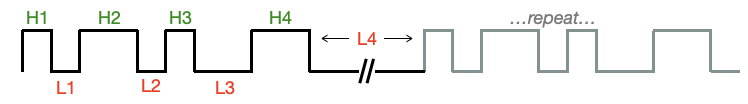
Since most RF/IR signals repeat the same train of pulses more than once, the duration of the last LOW phase should be extended to account for the delay between repeats of the pulse train. The following methods are used to construct the pulse train, set the number of repeats, set the duration of a tick, and start the transmission:
-
static void phase(uint16_t numTicks, uint8_t phase)-
appends either a HIGH or LOW phase to the pulse train memory buffer, which has room to store a maximum of 1023 phases. Requests to add more than 1023 phases are ignored, but raise a non-fatal warning message. Note that this is a class-level method as there is only one pulse train memory buffer that is shared across all instances of the RFControl object
-
numTicks - the duration, in ticks of the pulse phase. Allowable range is 1-32767 ticks. Requests to add a pulse with numTicks outside this range are ignored, but raise non-fatal warning message
-
phase - set to 0 to create a LOW phase; set to 1 (or any non-zero number) to create a HIGH phase
-
-
repeated phases of the same type (e.g. HIGH followed by another HIGH) is permitted and result in a single HIGH phase with a duration equal to the sum of the numTicks specified for each repeated phase (this is helpful when generating Manchester-encoded signals)
-
-
static void add(uint16_t onTime, uint16_t offTime)- a convenience function that create a single HIGH/LOW pulse. Implemented as
phase(onTime,HIGH); phase(offTime,LOW);as defined above, and subject to all the same limits and error-checks
- a convenience function that create a single HIGH/LOW pulse. Implemented as
-
static void clear()- clears the pulse train memory buffer
-
void start(uint8_t _numCycles, uint8_t tickTime) -
starts the transmission of the pulse train stored in the pulse train memory buffer. The signal will be output on the pin specified when RFControl was instantiated. Note this is a blocking call—the method waits until transmission is completed before returning. This should not produce a noticeable delay in program operations since most RF/IR pulse trains are only a few tens-of-milliseconds long
-
numCycles - the total number of times to transmit the pulse train (i.e. a value of 3 means the pulse train will be transmitted once, followed by 2 additional re-transmissions)
-
tickTime - the duration, in microseconds, of a tick. This is an optional argument with a default of 1𝛍s if not specified. Valid range is 1-255𝛍s, or set to 0 for 256𝛍s
-
Below is a complete sketch that produces two different pulse trains with the signal output linked to the ESP32 device's built-in LED (rather than an RF or IR transmitter). For illustrative purposes the tick duration has been set to a very long 100𝛍s, and pulse times range from of 1000-10,000 ticks, so that the individual pulses are easily discernable on the LED. Note this example sketch is also available in the Arduino IDE under File → Examples → HomeSpan → Other Examples → RemoteControl.
/* HomeSpan Remote Control Example */

#include "HomeSpan.h"             // include the HomeSpan library
#include "extras/RFControl.h"     // include RF Control Library

void setup() {

  Serial.begin(115200);           // start the Serial interface
  Serial.flush();
  delay(1000);                    // wait for interface to flush

  Serial.print("\n\nHomeSpan RF Transmitter Example\n\n");

  RFControl rf(13);               // create an instance of RFControl with signal output to pin 13 on the ESP32

  rf.clear();                     // clear the pulse train memory buffer

  rf.add(5000,5000);              // create a pulse train with three 5000-tick high/low pulses
  rf.add(5000,5000);
  rf.add(5000,10000);             // double duration of final low period

  Serial.print("Starting 4 cycles of three 500 ms on pulses...");

  rf.start(4,100);                // start transmission of 4 cycles of the pulse train with 1 tick=100 microseconds

  Serial.print("Done!\n");

  delay(2000);

  rf.clear();

  for(int i=1000;i<10000;i+=1000)
    rf.add(i,10000-i);
  rf.add(10000,10000);

  Serial.print("Starting 3 cycles of 100-1000 ms pulses...");

  rf.start(3,100);                // start transmission of 3 cycles of the pulse train with 1 tick=100 microseconds

  Serial.print("Done!\n");

  Serial.print("\nEnd Example");

} // end of setup()

void loop(){

} // end of loop()
↩️ Back to the Welcome page